Never Sign From a Satellite Image: Why Your Solar Design Must Be Site-Specific
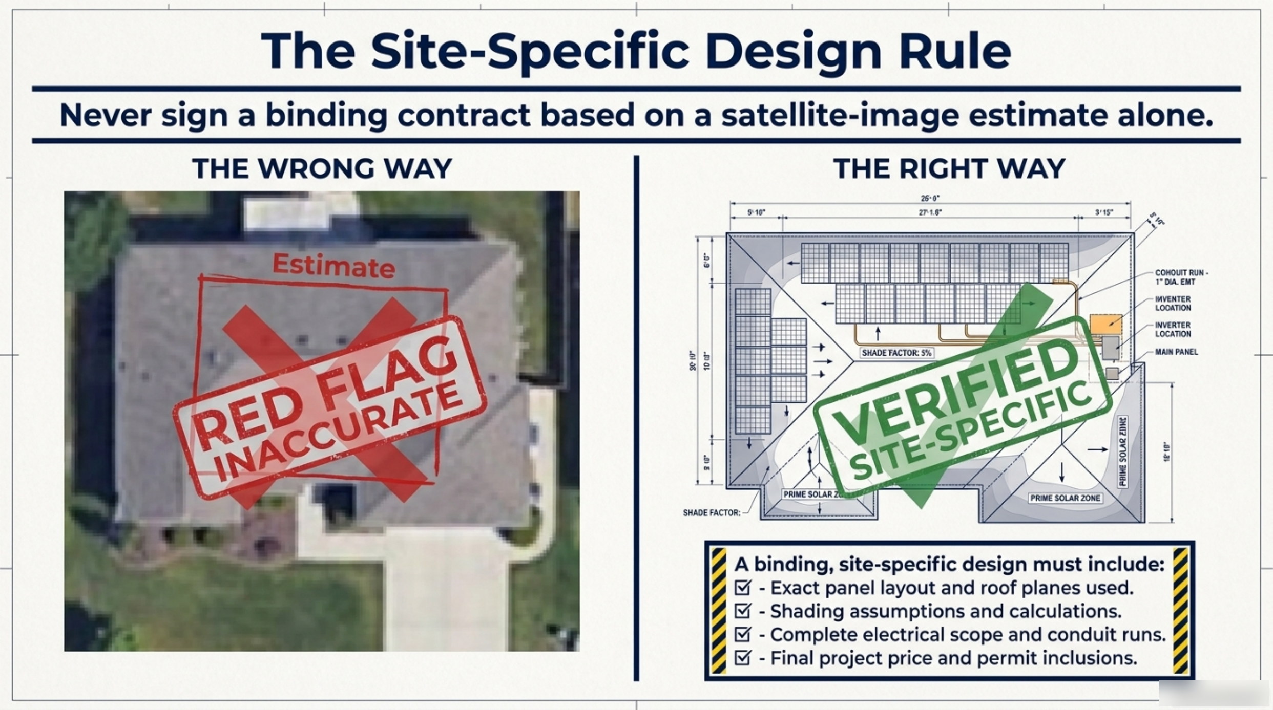
The rule on the slide is blunt: "Never sign a binding contract based on a satellite-image estimate alone." The rest of that page exists to show what the rule means in practice, because the illustration splits into two halves. On one side, a satellite view with an estimate marker dropped on a roof is stamped INACCURATE. On the other, a measured plan carries the words VERIFIED LOCATION and SITE-SPECIFIC.
The two halves are not two quality levels of the same document. They are different kinds of document. One is a bid produced from a picture. The other is a design produced from a site. The difference between them is the difference between a number you can hold someone to and a number that moves.
The short version
- Never sign a binding contract based on a satellite-image estimate alone — the slide states the rule plainly.
- A satellite image shows the roof outline; it does not show the panel interior, roof planes, stack shading or conduit paths.
- A site-specific plan carries a verified location stamp, a drawn conduit run, equipment locations and a measured shade factor.
- A binding design must include exact panel layout, shading assumptions and calculations, the complete electrical scope, and the final price with permit inclusions.
- If the design can change after signature, the price can change after signature.
What a satellite estimate cannot see
Satellite imagery is genuinely useful for a first conversation. It confirms roughly where the roof faces, roughly how much area there is, and whether the property is even a candidate. It becomes a problem at the moment it is treated as a survey. A picture taken from orbit contains none of the following:
- The inside of your electrical panel — available breaker spaces, busbar rating, and whether the service can carry the added generation at all.
- Roof planes and true dimensions — a plan view cannot show pitch changes between planes, rafter spacing, decking condition, or where structural reinforcement may be needed.
- Obstructions and their shadows — vent stacks, chimneys, skylights and satellite dishes each throw a shadow across a specific part of a specific roof plane at a specific hour.
- Trees, including the neighbour's trees — the shading that decides production in winter can come entirely from a canopy that is not on your deed.
- Where conduit and conductors can actually run — interior chases, attic paths, crawlspaces, trench routes, and which surfaces would have to be opened.
- Local permit and inspection requirements that shape the final scope and the final price.
Every one of those items changes the number. None of them is visible from above.
The two drawings, item by item
Look at what the slide's two halves actually contain. The estimate side is a satellite photograph with a crude red outline drawn over the roof, an estimate label, and a RED FLAG / INACCURATE stamp across it. There is no conduit, no equipment location and no shading figure, because none was calculated.
The site-specific side carries real drafting. The plan shows a conduit run specified as a one-inch diameter EMT run, drawn as an actual path from the array to the equipment. It marks the inverter location and the main panel location. It prints a measured shade factor on the drawing — five percent on this design — rather than an assumption. And it stamps the whole sheet VERIFIED LOCATION, meaning the geometry came from the property rather than from an image tile.
That is the difference summarised in one line: one sheet tells you a price, the other tells you a project.
The four items a binding design must include
The slide lists them, and the list is worth treating as a checklist you run against any plan set you are handed.
| Required item in the design | What it proves |
|---|---|
| Exact panel layout and roof planes used | That the array was fitted to measured roof geometry rather than to a rectangle drawn over a picture. |
| Shading assumptions and calculations | That the shade factor on the drawing came from an actual calculation, and can be checked or corrected. |
| Complete electrical scope and conduit runs | That the route from array to equipment to main panel was surveyed, including diameter and path of the run. |
| Final project price and permit inclusions | That the offer is comparable with another offer, with permit and inspection fees either inside the figure or named. |
The fourth item is the one homeowners forget. A design that describes the array and the wiring but not the price is a drawing, not an offer. A design that states a price without stating what permits and inspections are inside that price is an offer with an open end. Only when all four items are present is the document something you can compare against another installer's document on equal terms.
Why the word “binding” carries the weight
The slide does not warn against satellite images in general, and it does not warn against estimates. It warns against signing something binding on the strength of an estimate alone. Images and estimates are fine as the beginning of a process. The danger arrives when the loose version of the design is attached to a firm version of the contract.
So ask what happens when the design changes after signature. If the array shrinks, if a vent stack forces a panel move, if the conduit has to be re-routed, if the panel needs upgrading — who absorbs the difference? If the answer is that the price will be adjusted, the contract was never binding in the sense that matters to you. It was an option to renegotiate later, held by the other party.
What a clean paperwork trail looks like
When a proposal is genuinely site-specific, the file that arrives with it has a particular shape. It contains the plan set with the exact panel layout and the roof planes used. It contains the shading assumptions and the calculation behind the shade factor printed on the drawing. It contains the electrical scope: the single-line diagram, the conduit route, the inverter location, the main panel location, and any excavation the route requires. It contains the final project price with permit inclusions spelled out. And it contains a schedule that reflects that scope.
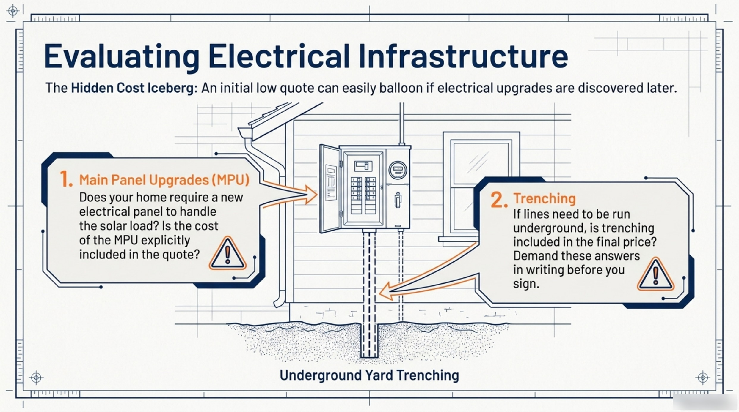
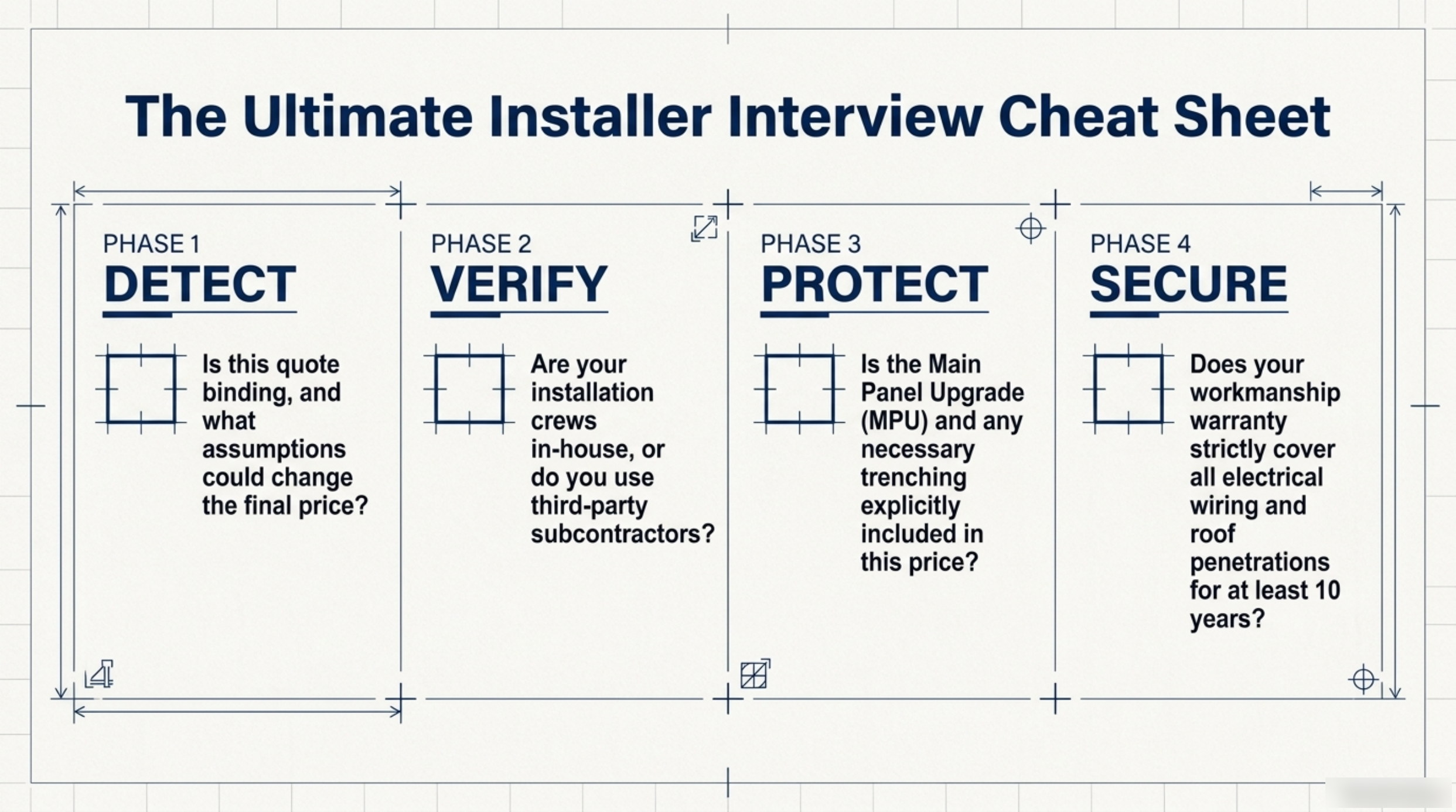
Comparing two installers is easy when both send that file and impossible when neither does. The satellite proposal is not worse because it is coarse; it is worse because there is nothing in it to hold anyone to. A copy of the design is also the reference point for later repairs, for roof work, and for any warranty claim — which is why the electrical scope in that file matters as much as the layout. The conduit run and equipment locations it documents are the same items the warranty discussion in Decoding the Three Warranties: 25+ Years, 10-30 Years and the 0.5% Degradation Cap turns on, and the panel scope it prices is the iceberg described in The Hidden Cost Iceberg: Main Panel Upgrades and Yard Trenching in a Solar Quote.
Frequently Asked Questions About Solar Design
Is a satellite estimate ever acceptable as a first step?
Yes, as a screening step. It can tell you whether a roof is worth a site visit and roughly what size array it might hold. It cannot tell you what the project costs, because it cannot see the panel, the obstructions, the shading, the conduit path or the permit scope.
What is a shade factor and why does the drawing print one?
A shade factor is the measured share of the sun's energy a specific roof area loses to obstruction over a year. Printing it on the plan forces that calculation to be explicit: a number on a drawing can be checked and corrected, while a verbal assurance that shading has been considered cannot.
Does a more detailed design cost more?
It reflects a different process, not necessarily a higher price. The worth of the site-specific sheet is that it removes the assumptions that would otherwise become change orders — the same assumptions that inflate a low quote once construction starts, as set out in The Hidden Cost Iceberg: Main Panel Upgrades and Yard Trenching in a Solar Quote.